Abstract. This paper presents the cause for inertia. We present a theoretical model of the mechanism of inertia and propose an experiment to test the new theory. Inertia is emerging at macroscopic level from the variable inertia of the microscopic particles which compose an object. The rectilinear uniform motion is just false impression caused by sinusoidal rectilinear motion. The mechanism of inertia reveals that inertia is quantized.
Introduction
The principle of inertia suggests two main points. First, it implies that an object cannot act upon itself to start moving uniformly or to stop from uniform motion. Secondly, it suggests that in absence of an external force acting on it an object moving rectilinearly can move only uniformly. In this paper, we argue against those conclusions, exposing that the object itself is the main cause of inertia. In the next section we present an experiment together with a theoretical model which describes the continuous motion of an object in absence of external forces. Since inertia is continuous motion in lack of external forces, we reason that our experiment describes in fact the mechanism of inertia. We show that inertia is an undulatory rectilinear motion of an object which is maintained by the object itself. The cause of inertia was veiled by the assumption included in its definition saying that an object moves uniformly after it is not acted upon by an external force anymore. We explain then that macroscopically we view motion as uniform due to the undulatory motion of the atomic particles which compose the object.
The Mechanism of Inertia
In order to investigate inertia we describe in Figure 1 a system consisting of two devices connected back-to-back along their common side OO’, with O being the origin of the reference system. We assume that the devices are mechanically or electromagnetically connected together being possible to easily disconnect the devices as need it during the experiment.
Each device consists of a plate of mass M and two weights of mass, m, that are attached on the plate and that can rotate around the connecting pivoting points on an arm of length r and of negligible mass. The weights of the first device (i.e. device 1) rotate in opposing direction of the weights of the second device (i.e. device 2). Within a device the weights rotate in opposing directions, one clockwise and another counterclockwise. We assume that all weights start rotating in the same time and with the same constant speed, v, and that they move synchronously. As they rotate, the weights will pull the devices with equal centrifugal forces, F.
Figure 2 shows the state of the system as the weights pass through the points located at 450 from their starting position shown in Figure 1. The entire system is in equilibrium remaining at rest because the centrifugal forces cancel each other out.
|
|
|
|
Figure 1 |
Figure 2 |


If we split de system along the OO’ axis, disconnecting the devices from each other at the moment when the weights pass through their starting position, then the system will lose its equilibrium. The components of the centrifugal forces on the y-axis, Fy, will not cancel each other anymore, exerting a traction force on each device. Note that the components of the centrifugal forces on x-axis, Fx, cancel each other out in each device. As a result of the Fy forces, the devices will move away in opposite directions on the y-axis. For device 1, the acceleration caused by the Fy forces is given by equation (1):
|
|
(1) |
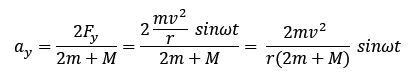
where ω is the angular velocity given by ω = v/r.
The equation of the speed vy with which device 1 moves along y-axis can be easily calculated as follows:
|
|
(2) |
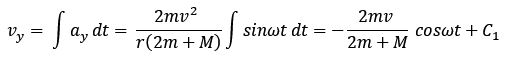
where C1 is a constant which can be calculated knowing that at the start time, t = 0, the device is at rest, vy = 0. Therefore C1 is given by:
|
|
(3) |
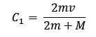
Rewriting C1 in equation (2), the speed of device 1 becomes:
|
|
(4) |
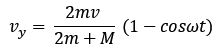
If we define the constant kmvr = 2mv/(2m + M), then equation (4) becomes:
|
|
(5) |
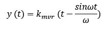
The coordinate of device 1 as it moves along y-axis is given by:
|
|
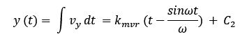
Where C2 = 0 since y = 0 at t = 0. Thus:
|
|
(6) |
The equation of speed is relevant for our analysis. It shows that an object moves continuously under its own action, accelerating and decelerating by itself until it stops and then it continues with this cycle forever as shown in Figure 3. The object moves on a straight-line. In short, we say that the object has a sinusoidal rectilinear motion.

Figure 3
The period of the motion depends on the angular velocity of the rotating subparts of the object according to the formulas known from classical physics: T=2π/ω. At high frequencies the motion would appear as uniform, an observer seeing only the envelope not noticing the stops of the object. Another factor which would make the motion appear as uniform is the constant kmvr which gives the amplitude of the speed variations. When kmvr is very small an observer would not be able to see speed changes, but he will see only a constant speed. Note that if we know the angular velocity and the constant kmvr, then all parameters of the motion – speed, acceleration, coordinates – can be calculated from equations (1), (5) and (6).
The formulas for the sinusoidal rectilinear motion could have been deduced by using an experiment with one single device set near a wall on a frictionless surface like shown in Figure 4.

Figure 4
The experiments described in Figure 1 and Figure 4 have been developed in Algodoo, a physics simulator, the simulation confirming the sinusoidal rectilinear motion deduced in this paper.
The case of the motion with multiple rotating objects in three-dimensional space is similar to the analysis done for the rotation of two weights in the two-dimensional space, since the components of the centrifugal forces on the x-axis and z-axis cancel each other out, the component on the y-axis remaining again the only relevant force. We also assume that other internal forces, such elastic forces, can create repetitive rectilinear motion, but their speed would change according to other formulas. We will not present in this paper the analysis of models using elastic forces or threedimensional coordinates, but focus on interpreting the results of the two-dimensional analysis of the sinusoidal rectilinear motion.
Consequences of Sinusoidal Rectiliniar Motion
There are several direct observations which result from the analysis of the experiment described in this paper.
1. Emergence of uniform inertia
The motion of device 1 appears to violate Newton’s laws of motion, but we must note that the object does not move uniformly as stated in the first law of motion. The sinusoidal rectilinear motion describes the mechanism of sinusoidal inertia, showing how objects keep moving continuously on a straight path in absence of external forces but using only internal forces. The rectilinear uniform motion emerges from the sinusoidal rectilinear motion for specific values of the angular velocity and of the constant kmvr. For formality only, we denominate Newtonian inertia as uniform inertia and the sinusoidal inertia as variable inertia. The macroscopic uniform inertia emerges from the microscopic variable inertia of the atomic particles. We note that uniform inertia can emerge at macroscopic level from macroscopic variable inertia as well.
2. Quantization of inertia
The graph of the speed displayed in Figure 3 shows that inertia of an object in sinusoidal rectilinear motion is quantized. Consequently, its kinetic energy is quantized as well.
3. Effects of sinusoidal inertia
Similar to uniform inertia, the sinusoidal inertia is not felt inside the moving objects. In addition, an object can start in and stop from sinusoidal rectilinear motion without an impact on the object or its components. Furthermore, knowing initial conditions, angular velocity and kmvr, the speed of a system in sinusoidal rectilinear motion can be calculated at any time from inside the system by measuring the position of the rotating weights.
4. Conversion from sinusoidal rectilinear motion to rest and uniform rectilinear motion
Let us assume that while device 1 is in sinusoidal motion after the split from device 2, we release the weights from the arms at the moment when they pass through their starting position. Since the device is just a plate without walls, the weights will fly away from the device as displayed in Figure 5.

Figure 5
When the weights are released, device 1 is at rest in the reference system. Since no other external or internal forces will act on it, the device will remain at rest while the two weights will fly out continuing to move uniformly with speed v.
This may appear to violate Newton’s third law of motion because the device remains at rest after it throws out mass without moving in the opposite direction. But for an external observer, his perception is dependent on either he sees (measures) the motion of device 1 as sinusoidal or uniform prior the release of the weights.
This method of procedure can have practical applications for ground and space transportation for stopping a ship from high-speed to full stop without destroying it.
5. Wave-particle duality
Variable inertia provides a mechanism explaining how particles move as waves without the need of a particular medium. That has been a question of physics since the discovery of light’s wave behavior. Particles in sinusoidal rectilinear motion do not “wave”, but they have a sinusoidal kinetic energy which pose challenges in measuring.
The interference patterns observed with light and electrons may be caused by particles’ interaction with the particles of the measuring sensors and not by interference as in the case of mechanical waves.
Similarly, the interference pattern and the anomalies of the dual-slit experiment have now better grounds for studies in order to eliminate the ambiguities of current explanations.
Conclusion
In this paper we presented a theory for the cause of inertia. We introduced the concept of variable inertia as the ability of an object to move continuously in sinusoidal rectilinear motion. We demonstrated mathematically that the object is able to maintain such motion without an external force but only through the use of internal forces, such as the centrifugal forces. Inertia, as known by classical physics, emerges from the variable inertia of the microscopic particles which compose an object. The concept of variable inertia brings a new view on motion and physics in general. The impact on few concepts of physics has been briefly presented, but we foresee that, in the light of the new information on inertia, a revision is required of several other concepts of physics.
References
-
Raymond A. Serway, Chris Vuille, College Physics, Brooks/Cole, 9th ed., Vol.1, p. 88, 2012
Note: The PDF version of this article can be downloaded from here: The cause of inertia.
The following video shows the simulation done in Algodoo for the device described in Figure 4.

